Monday, October 4, 2010

Good bearings

So, I finally figured out what the deal was with my accelerometer needing to be asked twice what the value was.

As it turns out, I wasn't actually giving the chip time to reply. I thought the micro would automatically handle receiving the data value, so I all I had to do was send the ACK at the end. In fact, the command that sends the ACK actually tells the micro controller to wait until the entire data byte has been transmitted, and then transmits the ACK.

So, when I was storing the value before sending the ACK, I was storing the value that I originally had in the register (the address of the accelerometer chip) and then waiting for the data and finally sending the ACK. Now, I've changed it so that it waits for the data and sends the ACK before storing the data value in the register.

How did I figure all of this out? With an O-scope! I simply modified my code so that it would give me a voltage spike on one of the output pins while it was reading the data from the register. What I noticed was that it was spiking before it was supposed to. Here's an example of what I mean:


Here's a plot of the two I2C lines while talking to the compass chip. The spike I was noticing was right after the "Chip Address and Read" segment, but before the "High Byte" that means that I never gave it time to actually read back the data!

Oh, what's that? You didn't know that I got the compass working too? Did you even read the title to this post?

Yep, it's working. Doing the reflow soldering was a little tricky because the compass doesn't really have QFN-24 footprint (I don't think it's a standardized footprint). The main difference is that the compass doesn't have the huge ground plate that QFN-24 provides. As seen here:


My solution was to simply cover the stencil with tape:

and carefully cut around the center holes:

Ta Da!

So, the compass works! It did need a little calibration. There's a routine that it can run wherein you're supposed to slowly spin it around while it collects data. When you tell the routine to stop (it recommends anywhere from 6 seconds to 3 minutes long), it does some math and figures out what magnetic fields are local to it (inherent in the circuit it's on) and what magnetic fields are due to the Earth. I didn't know I was going to need a calibration function, so I'll have to work that into the final design somehow.

The compass reports bearing as 1/10 a degree per digit. Here, you can see it displaying the top 4 bits of the compass bearing. Notice how dramatically it changes as the compass passes magnetic north.


Punctual, but Problematic

So, you haven't seen an update out of me in a while. This is because I've been struggling over the past week with getting my clock to return accurate, or at least consistently inaccurate results.

My test method was to use a little program that I wrote that would give me a 10 second count down before starting a timer that increments the LEDs once per minute. The idea was to use the 10 seconds to synchronize the timer with a timer known to be accurate and then let it run for a few hours and see how far off the minute mark it was. Take the number of seconds it's off, divide by total number of seconds elapsed, and multiply by 1 million to get the parts per million (ppm) accuracy.

See, every crystal oscillator needs to be "tuned" with some Load Capacitors. I tried my best to match the Load Caps to the 22pF rating on the crystal's spec sheet (even taking into account the parasitic capacitance on the breadboard), but I still couldn't get good results.

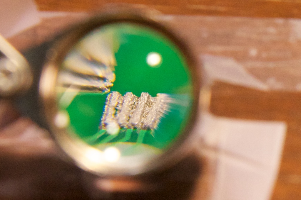
This is me measuring the capacitance that the crystal and chip would see (so, just the load capacitors). I tried to get it as close to 22pF as possible.

Note the two twisted wire pairs sticking up; each of those account for about 2-3pF and were very touchy.

The most upsetting part was how inconsistent my results were. The only certain thing was that wild variations in the capacitance made for wild variations in accuracy.

Well, it turns out that the timer on my iPod, which I assumed to be accurate, was far from it. After switching over to a Timex stopwatch, I got much nicer results. First, I managed to get around 30-35ppm consistently for over a day. Convinced that it was at least consistent, I tried lowering the load capacitance to see if I could improve accuracy. Dropping the 20pF caps for 15pF got me 20ppm accuracy.

I don't think I'll be able to exactly account for all of the capacitances that can interfere with my circuit's accuracy off hand. I think my official solution is going to be guessing the proper load capacitance in my final circuit, and replacing it with a different set of capacitors if it turns out not to be accurate. I'm actually fairly certain that this is how the pros do it. Build a prototype, figure out the best capacitance, and then repeat for 10000 more. At 20ppm, it would lose about 1.7 seconds a day. This is already perfectly acceptable, but I'm sure I can get it even closer when I build the final version.

On another semi-positive note, I got my accelerometer working!

So, convinced that my accelerometer was completely fried last time, I ripped it off the board to survey the damage. It looked like it had been soldered well, but it still didn't work. I was pretty certain that I had baked the chip too hard.

This time around, I wanted to be careful. I grabbed my Le Cruset pot and an infra-red temperature gun and attempted to simulate a reflow oven using a gas stove. The goal was to heat it at 200C for as long as it needed to melt the solder paste and then remove it immediately after.

I even got a video of it!


Well, after all of this, I was sad to learn that my chip still wasn't responding to any input. I simply couldn't get it to acknowledge its own address. This is exactly the behavior I got last time. Completely removing the chip got the same results.

The chip's address consists of a 7-bit number. When talking to it, you always add an 8th bit to indicate if you want to read from it (1) or write to it (0). The address is always sent first followed by the 8th indicator bit.

The address of the accelerometer was listed as 0011100. I was transmitting 00011100, using the aforementioned protocol for writing to the address, and the chip was ignoring me. Well, I was reading up on the I2C protocol at work today when I realized that I was an idiot.

In I2C, numbers are always transmitted most significant bit ("leftmost bit") first! That means that instead of sending 00011100, I should have been sending 00111000! Well, I tried this first thing when I got home, and I got the chip to talk!

Now, it still took me an hour to work out some of the details of getting something useful out of the chip, and I'm fairly convinced that the datasheet is wrong on this one...

The datasheet says that in order to receive a single byte from the chip, you must do the following:


Doing this resulted in me receiving the address of the chip as the current accelerometer data. This was the value that I loaded into the "TWDR" register that was supposed to be replaced by the data from the accelerometer. I was convinced that the whole thing just wasn't working and therefore not updating my register value. I struggled with this for about an hour or so (I had some other bugs along the way), but then I tried this:


This is for reading more than one byte from the slave. Note that the "master" (my microcontroller) sends an Master Acknowledge (MAK) after the first bit of data. Well, I found that for some reason, the first bit of data is always just the address that you sent it. The second piece, however, is what you really want.

I'm not really sure what's going on here. I never got the "single data" condition to return anything but an address, but I suppose I can live with just throwing out a garbage value to get to the good stuff...

The sheet even talks about a special mode of addressing (where you add 0x80 to the subaddress (register address) that you're looking for), that enables "multiple reads", but I'm still not entirely sure how that works. I think it's supposed to run through all the registers sequentially, but I haven't really found a use for it.

If more trouble crops up in the future, I'll look into these issues more, but as is, the accelerometer works exactly how I want to.

Here it is showing its Y data in binary!


It's 2's compliment with each digit representing about 18 milli-Gs. I turned it to 90 degrees and got back 0b111000 which works out to about 1.008G! Awesome!

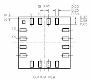
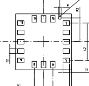
Now, the real sad part of this story is that, convinced that I had blown yet another chip, I went ahead and ordered another breakout board...two actually (just to be safe), all before realizing my addressing error. That's another $20 down the drain unless I use another .5mm pitch LGA-16 chip in the future. Also, I'll never know for sure, but I might have never fried the first chip after all...

Monday, September 27, 2010

Me and the Cap'n

So, it turns out that clock crystals need a "load capacitance" between each of their two pins and ground. I'm not entirely certain what these capacitors even do, but I do know that they are critical to keeping good time.

That nixie tube clock that I made originally had a clock crystal in it that had no load capacitors. This resulted in it being inaccurate.

Well, it isn't obvious from this video, but over the course of a day, it would lose 2 minutes of time or so. I ended up fixing the problem the lazy way and just used a "Crystal Oscillator" which is a three terminal device that takes Vcc and Gnd and gives you a pretty square wave. All of the load caps and everything are built in. Unfortunately, these guys are too big to fit in a watch, so I still have to figure out what the deal is with these load caps.

I'm getting a couple conflicting answers. Here's what the AVR data sheet has to say:

In the table above, it lists Ci as 18pF on tosc1 and 8pF on tosc2. I read somewhere that you can typically expect stray capacitance to be around 5pF or so, and the clock crystal's data sheet lists CL as 12.5. This makes the value of Ce around 0pF for tosc1 and 12pF for tosc2.

Hrm...

What does the crystal's data sheet have to say?

Soo... I'm pretty sure I can ignore the Rd because it's "as required" and my AVR data sheet makes no mention of a resistor like that.

So, this is a little ambiguous. I'm really not certain what to do. I think I might just follow the crystal's data sheet because the math for the AVR's data sheet is really weird. Besides, I'm fairly certain these capacitors won't saturate, so using bigger caps (like the 22uF) can't do too much damage, right?


Tik Tok

I have a clock!

So last night/today, I worked on getting the clock part of my AVR working. Here's the basic rundown.

The ATmega48A has what's called an asynchronous timer. A timer usually works by simply incrementing a number on a fixed interval of time and doing something special when that number reaches a certain value. Most of the time, the timer will just increment every time the processor's clock ticks. An asynchronous timer is special in that it can clock along at an entirely different pace.

While the processor is chugging along at 8MHZ, my clock timer is clicking along at 32.768kHz. How do I know this? Because I have it connected to a 32,768Hz clock crystal. Why such an odd number? Lemme explain.

So, let's say we increment our number at the 32.768kHz speed. The counter is an 8 bit number which means it will overflow after 256 clock ticks. That makes my overflow event happen at a rate of 128 times per second. That seems kind of fast. Luckily, there's something called a prescaler that can be set in the AVR's code. The prescaler sets how many clock ticks the chip should ignore before incrementing its counter by one. If you set this prescaler to 128, the clock will increment exactly once every second.

Clock crystals are incredibly accurate, so this dude should have no trouble keeping time.

Now what about power? Surely, I can't afford to be running a micro controller at 8MHz all the time. Luckily, the ATmega48A has the ability to enter a Power-Save mode where it will shut down all unnecessary actions and keep just the counter running. The idea is to have the chip wake up every second just for a millisecond or so and then go back into Power-Save mode for the remainder of the second. My actual code will have the chip waking up to update the time, but for now, I just have it blink an LED.

Here's a video of it in action. It only draws 1 microamp! (I had to actually unplug the programmer which was drawing 15 microamps)


The LED is extremely dim in the last part, because the multimeter will not allow enough current to pass when it's measuring on the 200 microamp scale.

The only thing I have left to look at as far as the clock goes is adding some load capacitors to my quartz crystal. These caps are necessary for keeping a crystal extremely accurate, so I'll need to figure out what's required before I trust my watch not to lose time.

Sunday, September 26, 2010

Dearly Departed

So today was something of a downer.

I received my LGA-16 breakout board from proto-advantage.com yesterday, and decided to give reflow soldering another shot with my digital accelerometer, the LIS33DE.

The LIS33DE is the first 3V chip I've used that cannot also run at 5V. Because of this, I decided to re-do my breadboard and get myself a 3V power supply. I found an old PC power supply that can output 3.3 volts which is close enough. I've got some mounting posts that I'm planning on bolting to the power supply to make it a little easier to manage, but for tonight, I just used some alligator clips to bring the 3.3V to my board.

Now, along this process, I did a very stupid thing. I left my micro controller and temperature probe connected to the board. I've always been a fan of hot-plugging in the face of adversity, but in this case, I was a little too reckless, and not only killed another micro controller, but also the temperature probe!

Luckily, I had backups of both, and while desoldering a SOIC part is tedious, it's by no means impossible.

What is very sad is my accelerometer. I'm not sure exactly what went wrong, but I was unable to get it to do anything intelligent. It wouldn't even acknowledge its own address.

Concerned that maybe I had some shorts in my solder, I tried applying some heat to the traces and letting the solder move around. I even added more solder, concerned that there was an open somewhere. I finally just ripped the chip off the board and found that neither was an issue (testament to my awesome solder paste stenciling skills).

What I'm putting on the death certificate though is "Got Baked."

I think I turned the toaster oven up a little too high (450F) for too long (like 10 minutes) and completely burned the chip up. I guess it makes sense that it's a little more sensitive than a temperature probe, huh... That also explains why the toaster smelled not only like burned food bits (like usual), but also like burned plastic. The poor guy didn't stand a chance.

I'm ordering a new chip and break out board. Proto-advantage usually takes like 2 weeks to deliver, so in the meantime, I'm going to continue working on the Real Time Clock, and the buzzers.

I'm going to be trying a different method for reflow in the future (especially before I even touch my $25 compass!) I've read on this page about doing reflow soldering in a skillet. The advantage here is that it will heat the chip from below and hopefully melt the solder paste before the chip gets too warm. Also, I learned that you're pretty much supposed to remove the chip as soon as the paste turns liquid. Now, I didn't really watch the chip when using the toaster oven in the first place, but the skillet should make the board much more visible.

Saturday, September 25, 2010

And the good lord said, let there be LED!

So, I haven't updated in a while (it's been one hell of a week), but just to get you up to speed. I got my new micro controllers and everything is just peachy there. Don't worry, I found a new home for the old ones:

More importantly, I got my LEDs!

These dudes are small. Like, you have no idea. Let my try to give you an idea with these pictures:

Such wasteful packaging

Everyone knows Washington had wooden teeth, but did you know that Lincoln had LED eyes?

I really had to mind my Ps and Qs dealing with these guys. Especially the Ps. At some point, the word "people" sent an LED flying.

It wasn't so small that I couldn't solder it, however. Let's just say that I'm very very glad I bought all the stuff I did, especially the glasses.

One technique I devised for holding the LED still was using tape sticky side up.
I wasn't very careful though, so I did melt the tape a little...

My technique was to flip the LED on its back, dab some solder on its contacts, and then heat the wire and touch it to the contacts. The flux pen was indespensible in this process. With enough flux on the led, I could just blob solder on and it would form two neat little mounds on the contacts. A little flux on the wire also helped make the joint.

I think my plan for the actual circuit is going to be to blob solder on the contacts, then flip the LED over and heat the footprint while lightly pressing the LED down.

So, if you've been keeping up with my blog, you've probably read about my concern that the LEDs wouldn't be bright enough especially when driving them at the requisite 30% duty cycle. I am no longer worried about this. In the following video, the LEDs switch between 30% duty cycle and red being on for 100% duty cycle and the other two being off. I also shake the camera around a little so you can get an idea of the switching frequency. Keep in mind that I intentionally slowed it down. I will presumably be driving them at the fastest frequency I can.


I actually did another test driving them at 20mA instead of 30mA (which is right at their absolute maximum). They are certainly bright enough even at 20mA which means I can use all of the awesome constant-current sinks that I found.

Next on my agenda is talking to the real time clock. I'm actually working in a lab tomorrow where I have to click a button every 30 seconds to take a picture with a digital microscope. I have an old mouse circuit board lying around, so I'm going to try to see if I can get my AVR's real time clock to click the button for me. I'll keep you posted.

Tuesday, September 21, 2010

I think I'm thinking too hard

I've been pondering this current-limiting nonsense all day, and I think I'm overthinking.

The issue is this: If I want to get maximum brightness out of my LEDs, I'm going to want to overdrive them a bit because I can run them at a maximum of33.3% duty cycle (if I have three LEDs lighting up at the same time). LEDs that are rated for 20mA of constant current might be rated for up to 100mA of peak current. Apparently, nobody make a 40+mA constant-current LED driver that runs at 3V. Oh well.

I think I'm going to bite the bullet on this one, and I think I'll be okay. I ordered a bunch of 0402 LEDs to play with (they're very very very small). I want to see how bright they are and how much abuse they can take.

I also ordered some banana plug binding posts so I can convert an old ATX power supply to a lab power supply.

A greener watch

I've been thinking more about energy savings with my watch.

I'm already going to be using some kind of Real Time Clock chip so that it only draws a tiny bit of precious power from my battery when in standby, but what about when I power the thing on?

Well, LEDs aren't current limiting. This means that unless you do something special, they'll draw a ton of current (and if you supply them with enough current) blow themselves up or at least severely shorten their lifespan. Because of this, you always need to add a current-limiting resistor to protect them.

Here's how it works:

Typical voltage drop across an LED is maybe 1.8V or so and most take around 20mA of current. If you supply with 3v (like my watch will), that means that you need to drop the last 1.2V across a resistor, keeping the current at 20mA. Ohm's Law says...

1.2V / .020A = 60ohm resistor

Now, that's pretty easy, but here's the ugly part:

Power = Current^2*Resistance = .02^2*60 = 24mW

24mW is quite a bit of power to be just throwing away. So, what's the solution? An LED current driver!

Current drivers are fancy IC devices that either source or sink constant amounts of current. I could basically set the current driver to source (or sink) exactly 20mA of current, and it would accomplish this much more efficiently than a resistor.

After hunting around for a bit, I found a likely candidate: the MAX6947 from Maxim.

Looking at its datasheet, it's I2C compatible, and can sink 20mA of current from 10 different ports (using this dude could also fix my port limitations. I could have current sourced from my micro controller and have it sunk into this chip. Sounds like a plan, but how efficient is it?

It draws nominally 3v and claims to draw around 1.3 uA in standby mode. Sounds good so far. What about when it's on? With one port set to 20mA constant current sink, it will draw 3.8mA of current. At 3V and 3.8mA, I'm looking at only 11.4mW.

It's a fairly large chip, so it might not be worth the 13mW power savings (which is only when the watch is on), but it does have a bunch of other cool features. You can digitally control PWM for the dimming of LEDs and it also will have no trouble sinking the current for a bunch of LEDs (which will be useful for my "flashlight mode" assuming my micro controller can source enough current to power all of them at once.

As one final calculation, if it draws 1.3uA at standby and 3.8mA when powered as opposed to an LED which draws 0A at standby and 24mA when powered. That means that for every 1 second of LED power, I could get around 54 minutes of standby time. Hrm...

One distinct disadvantage of this chip is that it can only sink 20mA of current. Ideally, because I'm going to have to flicker my LEDs at some frequency (because with the grid pattern, I can only light up one at a time), I'll want to drive them at their pulse current rather than their regular current. Brightness is proportional to current and because I will be effectively dimming these LEDs through pulse width modulation, I'll want to brighten them up as much as I can. An LED with a 20mA continuous conduction current might have a 50mA pulse current. So maybe I'll need a current sink with a little more kick.

Sunday, September 19, 2010

Soooo...what exactly happened last night?


So, after getting some sleep, I figured I'd update to discuss all the things I figured out.

Firstly, I got my new programmer!

Love the box-art on these things. Kind of makes me wonder how many MIPS my programmer can do (by the way, that's a Pb-free rainbow cannon).

So, I'm going to go ahead and talk about what I did wrong because I really need to remind myself of this more often. BYPASS CAPS!
(Yes, I drew this on the floor with chalk at about 8am.)

I was having this odd issue where my circuit was working until I disconnected the programmer. It turns out that the programmer produces a little bit of capacitance on the power rails, and disconnecting it removes this. The failure mode was that my LEDs would just light up at random and then freeze.

I made the poor assumption that the programmer was somehow chatting with the chip to make it work and removing it was messing up my code. Because of this, I disabled the External Reset Disable pin (RSTDISBL) which makes my programmer useless, however the code I already had programmed will still run when I power up the chip. Frantic, I tried something different with my second chip and set the debugWIRE Enable. debugWIRE, I later found out, is a protocol by which you can completely control a ATMEGA chip through a single wire. Unfortunately for me, you need a special (expensive) programmer to do this. I don't have such a programmer, so the chip is essentially useless to me.

I ordered some new chips.

In the future, I'll try bypass caps earlier. This happens time after time...

Anywho, it works! I2C is a really cool protocol. The whole thing is done with just two wires, so there has to be a lot of coordination as far as when to relinquish control of the bus. Each device must have a unique 7-bit address. The LM75A's address is 1001XXX where the Xs are set by pulling the A0, A1, and A2 pins high or low. I set mine all low so the address is 1001000. Reading the temperature basically goes like this:

ATMega48A microcontroller on left, LM75A temp sensor on the right.

Alright dudes, let's do this!
Is there a LM75A in the house that I can write to?

Yup
Aiiight, write this down, I wanna look at location 0x0h

Ain't no thang

Alright, let's do this again!
Is there a LM75A in the house that I can read from to?

Yup
Here's the first part
Got it
Here's the second part
Got it, and that better be the last one.
THAT'S ALL FOLKS!

Or... a less colorful version...


So doing this will return two bytes. The temperature is recorded in 2's compliment. It's a 11-bit number with the first 8 bits in the higher order byte and the last three in the highest bits in the lower order byte. This number, when multiplied by .125 should result in the current temperature in Celsius. The code that's now permanently frozen on my micro-controller outputs the high order byte of the temp readout on the Port D LEDs.


(Reading left to right) that's 00010110. There are three more bits on the low order byte that you can't see now, but they're not very significant for rough estimates. Let's just make them all zero. Let's see here...

10110000 in decimal would be 176. 176*.125C = 22C or 71.6F which is a totally reasonable temperature.

This thing is really fun to watch too.

Success! (sort of)

So, it's very very late right now, and I have other work I need to do before bed, so lemme keep this short.

My new programmer works, and I even got the I2C interface to work with the temperature probe!! (notice the "To Do" box on right)

The bad news is that in a fit of debugging fury, I managed to burn some bad fuses to my microcontrollers, so now I can't program them any more. I'm glad that at least managed to burn a good version of the code, so I currently have a gadget that can give me the temperature (in a round-a-bout way). I'm ordering some replacement micros.

Goodnight.

Friday, September 17, 2010

Can late-night musings cancel out other late-night musings?

So basically, I'm an idiot. There's no way my method of "doubling up" on LEDs is going to work.
No matter how you slice it, there's no way to light up just 1 LED.

I'm too tired to think about this anymore, but my solution will definitely involve some shift registers or a bigger micro controller.

Wednesday, September 15, 2010

Flow and Reflow are riding in a boat...

So I lied. I got my reflow soldering kit from proto-advantage.com and decided to get busy today instead of waiting for the weekend.
For some reason, I got two QFN-24 breakout boards. Bank error in my favor I guess...

I decided to start by trying the BMA145 analog accelerometer on the LGA-16 board. I opted for a digital accelerometer for my final design, so I figured I had nothing to lose. Besides, I have two of the chips, so I really can't mess it up that bad.

The reflow soldering method is very different from typical soldering. The pins on this thing are .65mm apart, so it's pretty much impossible to solder by traditional means. Instead, you have to apply solder paste which has the consistency of thick cake-icing. The paste consists of solder bits mixed with some kind of adhesive that will burn off at relatively low temperatures.

To apply the paste, you have to cover your board with a stencil so that only the copper pads are showing. Then you smear paste over the top. If you do it right, a tiny bit of paste is deposited in each hole. This is similar to screen printing T-shirts. Let's see how I did:
Eesh, that's no good. I've got all the traces touching. I made a mistake here with my setup. I had the stencil taped down over the board, but because the stencil was larger than the board, it sat unevenly and had a gap between the board and the stencil. The solder paste oozed into this gap and created the bridges. It's easy to wipe off with the included alcohol wipe. On to try two!
This time I added the two extra boards to keep the stencil straight.

So, the stencil wasn't lined up perfectly and I think the stencil is still bubbling up a little, so next time I'll hold it down with my tweezers very close to where I'm applying the solder paste. On to take three!

Um...

That's more like it! Now to place my chip carefully... wait, where is my chip? Oh crap, I must have dropped it. I have a backup, but I'd like to not lose it. Hm... it's not on the ground...

Oh! There it is!

Carefully placed...

Now to bake! The proto-advantage website recommends a toaster oven. I've got one of those around here somewhere...
This'll definitely work. Give it a few minutes at 450F aaaannndddd....
Presto!

I'm not 100% sure the joints are good. The spaces between the solder joints aren't super clean, so I'm a little worried.

I made my way up to lab to use their pretty equipment for testing. Here's my test rig:

And now for testing...

I DIDN'T FUCK IT UP!!!


Woooo! It performs as specified. There's a fair amount of noise which is to be expected when reading such small voltages, but I noticed about a 250mV difference between 0G and 1G. The chip's spec sheet says it should be .3V/G, so I guess it's working as advertised.

Now, there are a lot of redundant pins on the BMA145, so there's still a chance that I did mess it up and I just can't tell.

That's a lot of ground pins. I also just grounded SEL1 and SEL0 because I wasn't using the multiplexing output. Either way, I'm extremely satisfied with my result. Reflow soldering is not impossible by any means and it should let me build on a scale that I couldn't even imagine through conventional soldering.

Coming up next will be my compass. I'm a little afraid of messing that one up though because I'm using a QFN-24 socket for a weird chip. The socket standard includes a pad in the very middle of the chip seen here as a big square in the middle.
My compass chip (HMC6352) doesn't have this pad, and I think the solderpaste is going to be really messed up if I squish it under the insulated belly off the chip. I'm going to have to find a way to apply paste only to the edges. without getting it in the middle.

A challenge for another day...

Monday, September 13, 2010

A Nation of Frustration

Okay, so soon after I last posted, I started toying around with my old AVR mkII ISP programmer to see if I could get it to work again. It worked at some point in the past, but I've reformatted my laptop since then.

I will spare all the details suffice it to say that I spent about 4 hours trying to get the development environment set up, and for like 8 seconds, everything was swell-ish.

I know that the programmer worked at one point, but it didn't like my chip because my chip, the ATmega48A, varies slightly from the ATmega48 that its software is designed to work with. These two chips are identical as far as I care, but they have different signatures and the programmer was complaining about that.

I tried to write my own "driver" for the 48A simply by copying the 48's settings and adding the new signature when I must have messed something up.

Fast forward about 24 hours and I still don't know exactly what happened. Suddenly, rather than getting any device signature, my programmer was returning just Zeroes (0x00000000 to be exact) or sometimes zeroes with an odd number thrown in the middle.

I tried every possible debugging option I found online to come to the final conclusion that I must have busted the programmer. These things are designed to prevent overvoltage/overcurrent conditions, but I guess nobody's perfect.

It's also worth adding that I'm out of breadboard wire, so I've been using little scraps, and the only power supply I could find at that hour was a 4AA battery holder. You see, I tend to get into this mode where any sane person would give up and wait for a time when they have a clear mind and proper equipment, and I just continue to try more and more insane things as if one of them will miraculously work. It is entirely likely that some wires in this rat's nest of a bread board touched and messed something up.

I'm not entirely certain, but I have a hunch that there's a blown chip in my programmer.
Looking this chip up, I found that it's a quad SPST switch (MAX4712) which probably blew up when I shorted something, though I'll never be quite sure.

Either way, I'm ordering another programmer ($35 down the drain), and hopefully, I'll be up and running by next weekend. I'm just hoping that that actually is the issue and I didn't just waste $35 to be stuck with the same problems.

Other news for today. I got my new soldering iron!
It's amazing to work with.

I also got my temp sensors, the breakout board, and the flux pen. I've never used solder flux before, but it really is amazing stuff. It sucks up solder like a vaccuum. Soldering the sensor was a piece of cake.

I also got my new tweezers.

And more cranium accessories.

I'm going to give it a rest for now until my programmer gets here. After all, I'm still waiting for a lot of parts, and I'm also doing this whole school thing too. Maybe I'll sleep some...

Saturday, September 11, 2010

Doing Digital

So, earlier, I expressed an interest in changing my analog accelerometer to a digital one. I found an excellent candidate, the LIS33DE by ST devices, but it had this weird footprint.

My analog accelerometer claims to have a 4x4mm body LGA-16 footprint:

And the digital one has a 3x3mm body LGA-16 footprint:

Notice the weird layout? I suppose when you get down to 3x3mm, you can't pack the pins the same way.

For some reason, I thought this layout was extremely uncommon. I suppose I was mixing it up with the elusive PLCC-24 that I spent so long looking for. Turns out to be pretty easy to find.
This is great because the digital accelerometer should be much less of a hassle, and it saves me about .000000000007 square kilometers (or about 7 square mm) of space! I ordered my new accelerometer and the stencil kit.

I've also been looking at smaller buzzer options. I found one on digikey that is just 1/4 of my current buzzer's size, but I learned that buzzers can't really generate any arbitrary tone. They're really best when they are driven at their resonant frequency (usually 2kHz or 4kHz); at other frequencies, they're very quiet. Because of this, I don't think my guitar tuner is going to work quite how I want it to (besides, most guitar tuners produce both fundamental tones and overtones. Can't do that with a buzzer).

Instead of making a guitar tone generator, I think I want to actually try and add a microphone so that it can act like a real tuner. I've seen some tutorials online for how to perform a simple fast Fourier transform, and I could use the face of the watch as a tuning indicator.

I've got a few condenser mics floating around, so I'll play around with this at some point, but for the final version, I'll be using something like this as my mic.

Friday, September 10, 2010

Look at all these paaaarts!

So, I got the first of my digikey orders in today.

This included my analog accelerometer, the compass chip, and the buzzer among other things


I'd have to say that I'm surprised at how big everything is. After dealing with the little clock gears yesterday, these chips feel huge. I guess that's a good thing as far as handling them goes, but it's going to be really difficult to squeeze them all into the finished package.

I suppose first thing to change is going to be the buzzer. I had simply taken the buzzer off the MakerBot Watch which is much much bulkier than mine. I'm going to have to find a replacement at some point.

Also, On the right column of the blog, I've added a "to do" section which I will update with my upcoming parts orders and list of goals.

Huh, since adding that section, I realized that I really can't use the digital accelerometer that I had picked out because it's one of those weird LGA16 chips where the 16 are arranged in a 5x3 instead of 4x4 order. Gotta find a new one (or maybe I could stick with the analog, we'll see).

Thursday, September 9, 2010

The LED that burns twice as bright burns half as long

I was doing a little napkin-math to see what my power/space constraints would be.

Reading the specs of the CR2032 battery, I found that the maximum rated continuous current is 1mA and the max pulse current is 10mA. Typical full-size LEDs take something like 20mA. But even if the LEDs only took 5mA, that's too much when you factor in all the other crap on the watch.

I'm not too worried about it at the moment though. I'm assuming I can push the battery a little because I won't be drawing boatloads of current out of it continuously. I took the back off my binary watch and found that its massively bright bank of LEDs runs off a CR2032 and it might have up to 8 LEDs on at a time.

As far as space constraints go, I'm glad to see that surface mount LEDs are so diverse. Metric package sizes are usually listed by length and width as measured in mm. For example, a 1206 is 1.2mm by .6mm. My watch face is about the size of a gold dollar coin or 26.5mm across. That gives me an outer circimference of 8.32cm or around 1.4mm per LED. Seeing how I can pack LEDs very very close together, I should have no issues if I pick packages like an 0402 (that's as small as I could find).

My other main concern is brightness. Most of the LEDs I've been looking at are around 5-10mcd, but I have no way to judge exactly how bright that will be. I suppose I'll have to worry about that later.

When is a wrench not a wrench?

So it turns out not only was the wrench not needed, but if it was, I got the wrong kind. All of the watches I've dealt with are opened by prying off the backing. This is how I've destroyed a number of screw drivers, so I thought a dedicated tool might do a better job. Turns out I was wrong. This wrench is for "jaxa" style watches which have little grooves on the backing which line up with the wrench. The back is then unscrewed.

Whoops. There goes $6...

Edit, actually, someone on my hall has a slide rule watch which wasn't slide ruling very smoothly. Using my new wrench, I was able to take the backing off her watch and apply some lubricant to the slide rule gear. $6 well spent.

From the Ministry of Very Small Things

So, I got my watch and watch case wrench today and decided to put them to use.

The case wrench came in a nice fancy box.

The watch is pretty sleek.

Sleeker in fact than both of my binary watches. It looks like it's going to be pretty tight in there.

As it turns out, this watch is "water resistant" not "water proof", so I didn't even need the wrench to get the back off. I just pried it off with a screw driver.

Inside, I found that they hardly used any of the space inside the watch. There is just a tiny little cluster of gears in the middle.

Wanting to preserve as much as the turn dial-knob as possible (this will serve as my button), I carefully extracted the parts bit by bit. To unscrew the tiny little flat heads, I had to use a razor blade to get them loose followed by more unscrewing by one of my huge-by-comparison flathead screwdrivers.

Very small screw and gear.

Overall, it was a pretty good experience. I managed to save all of the knob which will serve as my button.

The only issue I see is that the part of the watch that kept the knob from falling out no longer exists, so I'm going to have to work out some method of keeping the knob in. Most likely, I will just trim down the shaft (so it doesn't needlessly take up so much space) and then glue something to it to make it too wide to pull out all the way.

All in all, this was my first experience so far dealing with something very small, and I'm really glad I got my goggles (and the tweezers that are on the way; my current tweezers are terrible). I also got some good practice taking pictures of very small things.